Force Directed Layout Algorithm
The force directed approach
to VLSI placement, layout and routing offers significant gains in speed for
many graph problems. A circuit is first modeled as directed graph. The
nodes in the graph are iteratively positioned by assigning attractive and
repellent forces with respect to the other nodes in the graph. The motion is
similar to how charged particles behave in real life physical systems. As time
progresses, the nodes reach a stabilized position and the algorithm is terminated.
Figure 1 shows a VHDL description of a logic circuit. Figure 2 shows the
stabilized position of the nodes resulting from the algorithm.
|
library IEEE; use IEEE.std_logic_1164.all; entity c17 is port( PI1, PI2, PI3, PI4, PI5 : in std_logic; PO1, PO2 : out std_logic); end c17; architecture Structural of c17 is component NAND2 port( E1, E2 : in std_logic; A : out std_logic); end component; signal G10, G11, G16, G19 : std_logic; begin G10_NAND2 : NAND2 port map( E1 => PI1, E2 => PI3, A => G10); G11_NAND2 : NAND2 port map( E1 => PI3, E2 => PI4, A => G11); G16_NAND2 : NAND2 port map( E1 => PI2, E2 => G11, A => G16); G19_NAND2 : NAND2 port map( E1 => G11, E2 => PI5, A => G19); G22_NAND2 : NAND2 port map( E1 => G10, E2 => G16, A => PO1); G23_NAND2 : NAND2 port map( E1 => G16, E2 => G19, A => PO2); end Structural; |
Figure 1 – Description of VHDL File
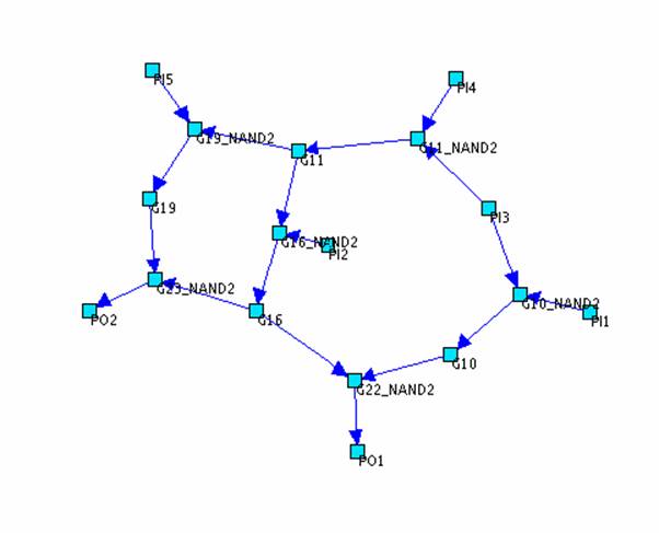
Figure 2 – Layout Obtained from Force
Directed Algorithm